|
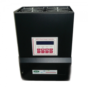
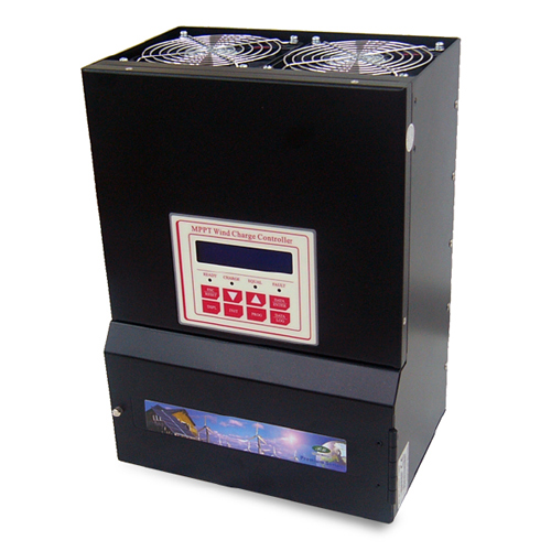
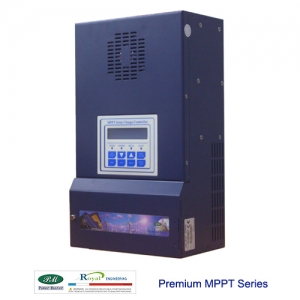
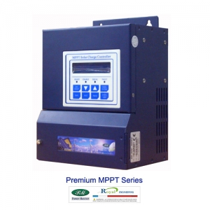
MODEL |
|
|
ELECTRICAL
|
|
Input Voltage
Range (no damage) |
|
|
Operating
Input Voltage Range from PMG
(Permanent Magnet Generator) |
|
Optimal Range:
20 ~ 180 VAC |
|
System voltage
ratings |
|
|
Current
ratings-Battery Charge Control |
|
|
Max. Current
in the Brake Resistor |
|
|
DC Output
Voltage Range |
|
|
|
|
Automatic
Brake Function |
5 Level:
200, 210, 220, 230, 240 VDC
(Adjustable)
![]() Can be
customized for the wind turbines Can be
customized for the wind turbines |
|
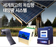
Maximum
Wind Turbine Capacity |
Charging 48
VDC Batteries |
|
Charging 36
VDC Batteries |
|
Charging 24
VDC Batteries |
|
Charging 12
VDC Batteries |
|
|
Charge
Regulation Modes |
Bulk,
Absorption, Float, Auto/ Manual Equalization |
|
Battery
Temperature Compensation |
5.0 mV per °C
, per 2 volt cell |
|
DC to DC
Conversion Capability |
|
|
|
|
|
|
|
|
Display
Status |
Built-in
2-line, 20-character LCD with backlight
LCD status screen displays input
voltage and
current, output voltage and current, charge-mode,
Battery SOC
|
|
Data Logging
|
Logs energy
harvested for 90 days, LCD displays WH, KWH, AH |
|
Energy Monitor
|
LCD shows SOC,
AH, WH, and present charge or discharge current. A 50mV/ 500Amp shunt is
required to use |
|
Auxiliary
Relays |
Two
independent relays with from A ( SPST ) contacts for control of external
devices. Contact rating is 3 Amps, 50VDC |
|
Operation
Temperature |
Full Power
Output to +50 °C ambient |
|
Standby Power
|
|
|
Relative
Humidity |
|
|
MECHANICAL
|
|
Dimensions
(mm) [H x W x L] |
|
|
Weight |
|
|
Optional
Diversion Load |
|
|
Specifications
subject to change without notice |


 이 상품을 본 고객들이 가장 많이 구매한 다른 상품